Hitesh No Comments

Desalination of water: pumps, process and sea water purification guide

Table of Contents

  1. Why pumps decide whether a desalination plant succeeds
  2. What does desalination actually involve?
  3. The desalination plant process, stage by stage
  4. Which pumps are used at each stage of desalination of ocean water?
  5. How to select high-pressure pumps for desalination
  6. Why material choice makes or breaks a sea water purification pump
  7. Operating and maintaining desalination pumps for the long run
  8. How Sintech engineers pumps for desalination of seawater projects
  9. Conclusion
  10. FAQs

Pumps are the working heart of every desalination plant. They lift ocean water, push it through filters, and raise it to the pressure that forces salt out across a membrane. This guide walks through the full desalination plant process, the pump used at each stage, how to select high-pressure pumps for desalination, and how to keep them running in harsh, saline conditions.

[ultimate_heading main_heading=”Introduction” alignment=”left” margin_design_tab_text=””][/ultimate_heading]

A desalination plant is, in many ways, a chain of pumps. Take any one of them offline and the whole line stops. That is why engineers who design, buy, or run these plants spend so much time thinking about pumping. The membranes get the attention, but the desalination pumps are what make the membranes work.

If you are specifying equipment for a coastal water project or maintaining an existing plant along the Indian coast, this guide is for you. We will move through the desalination of water from intake to clean output, look closely at each pump’s job, and cover the practical questions of selection and day-to-day operation.

[ultimate_heading main_heading=”Why pumps decide whether a desalination plant succeeds” alignment=”left” margin_design_tab_text=””][/ultimate_heading]

Desalination is energy-intensive, and most of that energy goes into pumping. Pushing seawater through a reverse osmosis membrane needs roughly 55 to 80 bar of pressure. That is the single largest power draw in the plant. So even a small gain in pump efficiency shows up directly on the electricity bill, month after month.

There is a second reason pumps matter here more than in an ordinary water supply. Seawater is corrosive, gritty, and never stops moving through the plant. The pumps run almost continuously, often 24 hours a day. A pump that fails early, leaks, or pits in the salt does not just cost a repair. It interrupts the water supply that a city or industry depends on.

[ultimate_heading main_heading=”What does desalination actually involve?” alignment=”left” margin_design_tab_text=””][/ultimate_heading]

Desalination of water simply means removing dissolved salts and minerals from saline sources to make the water fit for drinking, agriculture, or industry. The two most common sources are the open ocean and brackish groundwater near the coast.

The headline numbers explain why it matters. About 97% of the planet’s water is saltwater, and average seawater carries roughly 3.5% salt far too much for people to drink. Seawater purification through desalination turns that abundant, unusable resource into a reliable supply. For water-stressed coastal regions, the desalination of ocean water has shifted from a luxury to basic infrastructure.

Two main technologies do the work. Thermal methods boil seawater and condense the vapour. Reverse osmosis, or RO, forces water through a semi-permeable membrane that traps the salt. RO now dominates new plants because it uses less energy, and almost all of that energy is delivered by pumps. So seawater purification at scale is, at its core, a pumping problem with a membrane attached.

[ultimate_heading main_heading=”The desalination plant process, stage by stage” alignment=”left” margin_design_tab_text=””][/ultimate_heading]

Understanding the desalination plant process makes pump selection far easier, because each stage asks for a different kind of pump. Here is how the desalination of seawater moves through a typical RO plant.

First comes intake. Raw seawater is drawn from the sea through intake structures and lifted toward the plant. This calls for high flow at modest pressure, since the goal is simply to move a very large volume of water inland.

Next is pretreatment. The raw feed passes through filters that strip out sand, silt, marine organisms, and other particles. Booster pumps push the water through these filters, and backwash pumps periodically clean the filter beds by reversing the flow.

Then comes the heart of the desalination plant process: high-pressure feed. Filtered seawater is raised to RO operating pressure and forced against the membranes. The membrane lets pure water pass while holding back the salt. This is where high-pressure pumps for desalination do the heaviest work in the entire plant.

After the membrane, two streams leave. One is the product water, clean and low in salt, which is pumped to post-treatment and storage. The other is brine concentrated reject water which must be circulated and safely discharged. Many plants also recover energy from this high-pressure brine to cut power use.

So the desalination of ocean water is not one pumping task but several, each with its own flow, pressure, and fluid condition. That is the key insight behind good pump selection.

[ultimate_heading main_heading=”Which pumps are used at each stage of desalination of ocean water?” alignment=”left” margin_design_tab_text=””][/ultimate_heading]

Now to the practical part. Different stages need genuinely different machines, and the right pumps for desalination are matched to the duty, not bought off a single shelf.

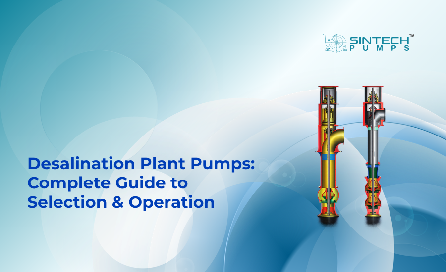
For seawater intake, the plant needs to move enormous volumes at low to moderate head. A split-casing double-suction pump is well suited here. Its twin-suction design balances the load on the shaft and handles very high flow with low vibration, which is exactly what a continuous intake duty demands. For installations where floor space is tight or the suction level changes with the tide, a vertical mixed flow pump (SVMF) is the stronger choice. Sintech’s SVMF series can deliver flows up to 44,000 m³/hr at heads up to 300 m, sits submerged so it never loses prime, and resists cavitation at the inlet.

For low-pressure transfer and filter feed, the water needs to move from pretreatment toward the high-pressure stage at moderate head. A horizontal mixed-flow pump (SMF) fits this duty cleanly. Sintech’s SMF series handles up to 7,000 m³/hr at around 45 m head, with a semi-open, hydraulically balanced impeller that copes with lightly turbid or saline water. Standard centrifugal process pumps (CPS), built to ISO 2858 and ISO 5199, cover transfer and flushing duties around the plant.

For the high-pressure RO feed, only a purpose-built machine will do. A multistage high-pressure pump raises filtered seawater to the 55 to 80 bar needed to drive reverse osmosis. Multiple impeller stages build the pressure in steps, which is why these are the high-pressure pumps for desalination that define the plant’s output and its energy use.

The remaining duties are handled by auxiliary desalination pumps: backwash pumps for cleaning filters, brine recirculation pumps that run at modest head, flushing pumps for membrane cleaning cycles, and dosing pumps for precise chemical addition such as anti-scalant and pH correction. None of them is glamorous, but a weak auxiliary pump can stall the whole line just as surely as a failed main pump.

[ultimate_heading main_heading=”How to select high-pressure pumps for desalination” alignment=”left” margin_design_tab_text=””][/ultimate_heading]

Choosing high-pressure pumps for desalination comes down to a handful of questions, answered in order.

Start with flow and head. Size the pump to the plant’s design output and the membrane’s required operating pressure, then check where that point falls on the pump curve. You want the duty point at or near the Best Efficiency Point (BEP), because running far from BEP wastes energy and shortens the life of the pump.

Next, look hard at suction conditions. Net Positive Suction Head, or NPSH, is the margin that keeps the pump from cavitating. Cavitation vapour bubbles forming and collapsing inside the pump pits impellers and destroys efficiency. Seawater intakes are especially prone to it, so the available NPSH at the site must comfortably exceed what the pump needs.

Then consider efficiency over the plant’s life, not just the purchase price. On a high-pressure feed pump drawing hundreds of kilowatts, even a two- to three-point efficiency gain saves a substantial sum every year at Indian industrial power tariffs. Pairing the high-pressure stage with an energy recovery device compounds those savings.

Finally, confirm the materials and the standard the pump is built and tested to. For India, look for testing to IS 9137 or ISO 9906, which verify that the pump actually meets its rated curve before it ships. Reliable pumps for desalination are proven on a test bed, not just on paper.

[ultimate_heading main_heading=”Why material choice makes or breaks a sea water purification pump” alignment=”left” margin_design_tab_text=””][/ultimate_heading]

This is where many specifications quietly go wrong. Seawater is one of the most aggressive fluids a pump will ever handle. It carries chloride, dissolved oxygen, silt, and marine life, and it attacks ordinary metals quickly.

Standard 304 or 316 stainless steel can suffer pitting and crevice corrosion within months in raw seawater. For wetted parts, the casing, impeller, and shaft sleeves, Duplex stainless steel such as SS2205 or Super Duplex such as SS2507 is the dependable choice. These alloys combine high strength with strong resistance to chloride attack, which is why Sintech machines the wetted components of its seawater pumps from Duplex grades.

Material selection is matched to the water itself. Salinity and temperature both influence the right grade, and the brine side runs even harsher than the feed side because the salt is concentrated. Getting the metallurgy right is just as important as getting the hydraulics right. A poorly specified pump may pit and fail within a year, while a correctly built Duplex pump can run for decades. This is the difference between a cheap pump and a low-cost one, and it shapes the real economics of the desalination of ocean water.

[ultimate_heading main_heading=”Operating and maintaining desalination pumps for the long run” alignment=”left” margin_design_tab_text=””][/ultimate_heading]

Selection gets the plant started. Operation keeps it profitable. Because desalination pumps run nearly around the clock, small habits make a large difference over the years.

Keep the intake clear. Debris, weed, and silt at the suction starve the pump and raise the cavitation risk. Monitor vibration and bearing temperature, since a rising trend usually warns of trouble long before a failure. Watch the pump’s operating point too; if flow or pressure drifts from the design curve, efficiency is leaking away, and energy cost is climbing.

For the high-pressure stage, mechanical seals and wear rings deserve close attention, as they take the brunt of the pressure and the salt. Vertical intake pumps that sit submerged tend to run cooler and resist cavitation, which is one reason they suit continuous seawater duty so well.

When a pump has run well past its design life, a full replacement is not always the answer. A pump health check and energy audit often reveal that retrofitting or overhauling restores most of the lost efficiency at a fraction of the cost. For plants under pressure to cut power bills, that is frequently the smartest first move.

[ultimate_heading main_heading=”How Sintech engineers pumps for desalination of seawater projects” alignment=”left” margin_design_tab_text=””][/ultimate_heading]

For desalination specifically, the portfolio maps neatly onto the plant: split casing double suction and vertical mixed flow SVMF pumps for high-volume seawater intake, horizontal mixed flow SMF pumps for low-pressure transfer and backwash, multistage units for the high-pressure RO feed, and centrifugal process pumps for transfer and flushing. 

Wetted parts are built in Duplex and Super Duplex for life in salt. Just as important, Sintech’s engineers will match the grade and the curve to a plant’s actual salinity, temperature, and flow rather than handing over a catalogue number. That application-first approach is what separates a pump that fits from a pump that lasts.

[ultimate_heading main_heading=”Conclusion” alignment=”left”][/ultimate_heading]

Desalination is no longer a frontier technology in India; it is steadily becoming part of how coastal cities and industries secure their water. And behind every litre of clean output sits a carefully chosen pump doing quiet, demanding work. Get the desalination pumps right, the correct type at each stage, the right metallurgy for the salt, and disciplined operation and a plant rewards you with reliable water and predictable running costs for years.

If you are planning a new plant, comparing suppliers, or rethinking an ageing system, it is worth talking the choices through with engineers who have specified these pumps before. The Sintech application team can review your process conditions, recommend the right pump for each duty, and help you weigh efficiency against lifecycle cost.

[ultimate_heading main_heading=”Frequently Asked Questions” alignment=”left”][/ultimate_heading]

1. What is the desalination plant process?

The desalination plant process removes salt from seawater in stages: intake, pretreatment filtration, high-pressure reverse osmosis through a membrane, and post-treatment of the product water. Pumps drive every stage, and the high-pressure feed pump does the heaviest work by forcing water across the membrane.

2. Which pumps are used for the desalination of seawater?

The desalination of seawater uses several pump types. Split casing double suction and vertical mixed flow pumps handle intake, horizontal mixed flow pumps manage transfer and backwash, and multistage pumps deliver the high pressure for reverse osmosis. Auxiliary pumps cover brine recirculation, flushing, and chemical dosing.

3. What are high-pressure pumps for desalination?

High-pressure pumps for desalination are multistage centrifugal pumps that raise filtered seawater to roughly 55 to 80 bar. That pressure forces water through the reverse osmosis membrane while the salt is rejected. They are the largest energy consumer in the plant, so efficiency directly affects running costs.

4. What materials are best for seawater desalination pumps?

Wetted parts of desalination pumps should use Duplex stainless steel like SS2205 or Super Duplex like SS2507. These alloys resist the chloride pitting and crevice corrosion that quickly damage ordinary 304 or 316 stainless steel in seawater, giving far longer service life in continuous saline duty.

5. How is seawater purification different from normal water treatment?

Sea water purification must remove dissolved salt, not just suspended particles, so it relies on reverse osmosis at very high pressure. Ordinary water treatment handles fresher sources at much lower pressure. This is why the desalination of water from the ocean needs specialised high-pressure and corrosion-resistant pumps.

6. How can plants reduce the energy cost of pumps for desalination?

Choosing efficient pumps for desalination that run near their Best Efficiency Point is the first step. Adding an energy recovery device on the brine stream, monitoring the operating point, and retrofitting worn pumps all cut power use. On large high-pressure pumps, small efficiency gains save significant money annually.
Hitesh No Comments

Boiler feed pumps for thermal power plants: selection, sizing, and maintenance

Table of Contents

  1. What is a boiler feed pump, and why does it matter in a thermal power plant?
  2. How does a boiler feed pump work in a thermal power plant?
  3. Types of boiler pumps used in power stations
  4. How to select the right boiler feed pump: key parameters
  5. How to size a boiler feed pump correctly
  6. Boiler circulation pump vs boiler feed pump: what is the difference?
  7. Common maintenance challenges for boiler feed pumps in power plants
  8. Conclusion
  9. FAQs

A boiler feed pump is the high-pressure pump that pushes deaerated feedwater from the deaerator into the steam generator, usually somewhere between 150 and 300 bar in a utility-scale plant. Get the choice wrong, or skip the maintenance, and you’re looking at an unplanned outage that costs lakhs an hour. This guide covers how to pick one, size it, and keep it running, and where most plants go wrong on all three.

[ultimate_heading main_heading=”What is a boiler feed pump and why does it matter?” alignment=”left” margin_design_tab_text=””][/ultimate_heading]

Steam runs a coal, gas, or biomass plant. Simple as that. And behind every tonne of steam there’s a feed pump grinding away around the clock, under serious pressure, keeping water moving into the boiler drum.

What it does isn’t complicated. It takes deaerated feedwater off the low-pressure side and shoves it into the high-pressure boiler circuit. To do that it has to beat the boiler’s own pressure plus every bit of friction in the feedwater piping. Gentle work, this is not. A 210 MW coal plant will ask its feed pump to work against a total dynamic head (TDH) of 2,000 to 2,500 metres, moving 600 to 1,000 cubic metres an hour. Build any weakness into that pump and it won’t stay hidden for long.

And here’s why everyone obsesses over these boiler pumps. A forced outage on a 210 MW unit burns roughly ₹15–20 lakh an hour in lost generation. The feed pump? Nearly always in the top five things on a plant’s failure-risk list. So when you choose one, you’re not really making a purchasing call. You’re deciding how many hours a year the plant gets to run.

[ultimate_heading main_heading=”How does a boiler feed pump work in a thermal power plant?” alignment=”left” margin_design_tab_text=””][/ultimate_heading]

The feedwater circuit is a loop. Condensate comes out of the condenser hotwell, gets heated and deaerated across a string of heat exchangers and the deaerator, and by the time it hits the feed pump suction it’s sitting at 120–170°C and 6–12 bar absolute.

The pump then drives that hot water through a row of impeller stages, putting energy in at each one, until the discharge pressure clears boiler drum pressure plus the friction in the economiser, control valves, and piping. It can’t just sit in one flow, either. Plants swing their load all day, so the pump has to track those changes without surging or sliding down into a low-flow zone where things start to go wrong.

Now, the one thing that trips people up: Net Positive Suction Head Available, or NPSHa. The feedwater is hot, right on the edge of boiling, so the smallest pressure drop at the suction can flash it to vapour and you’ve got cavitation in seconds. That’s the whole reason the deaerator sits up high above the pump. It isn’t an arbitrary height. Someone calculated it to keep NPSHa at least 2–3 metres above the pump’s required NPSH (NPSHr) at full flow. Put it all together, hot water near saturation, very high pressure, tight suction margins, and you’ve got one of the nastiest duties any power plant pump has to handle.

[ultimate_heading main_heading=”Types of boiler pumps used in power stations” alignment=”left” margin_design_tab_text=””][/ultimate_heading]

What you pick depends on three things: plant size, boiler pressure, and whether the cycle is sub-critical or supercritical.

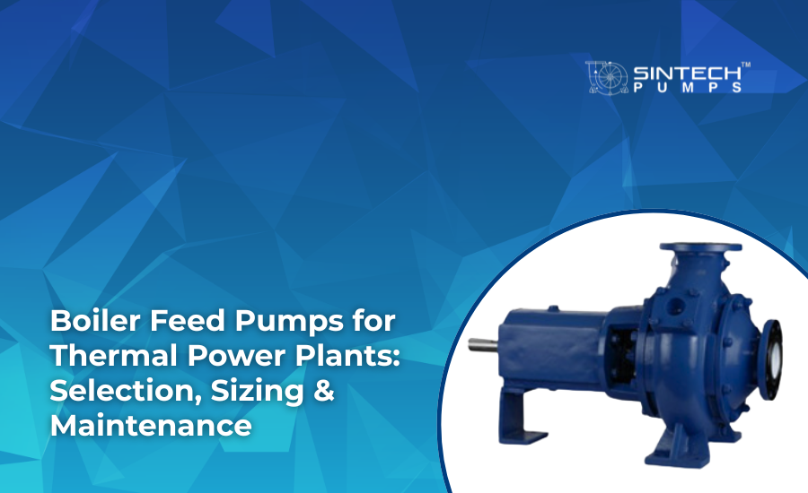
For plants up to 210 MW, the horizontal multistage centrifugal pump does most of the work. It stacks several impeller stages in a single between-bearings casing so it can make the head you need without spinning stupidly fast. Go for the split-casing version and maintenance gets a lot kinder: pop the top half of the casing off and you’re looking at the impellers without breaking into the piping.

Supercritical plants above 250 bar move to barrel-type, double-casing pumps. There’s an inner barrel sitting inside an outer pressure vessel. Pricier to build, no question, but they hold up where the pressures would worry an ordinary casing.

Smaller captive plants, say 5 to 30 MW, often go vertical inline. Tight floor space, lower pressures around 30–80 bar, and a vertical multistage suits that fine.

Strip away the format and it’s the same animal underneath: a multistage centrifugal pump. Every stage adds a set chunk of head, usually 150 to 250 metres, depending on impeller size and speed. Run a six-stage at 2,980 RPM and you’ll comfortably see 1,200–1,500 metres of TDH. Bolt on two more stages and you’re at utility pressures.

The thing that separates a feed pump you can trust from a run-of-the-mill industrial multistage is the metal. Wear rings, balance discs, shaft sleeves, in feed duty these are usually 13% chromium stainless or something tougher, because hot water moving fast for months on end will eat carbon steel alive. Sintech’s multistage high-pressure pumps are designed around this exact duty, alloys and stage hydraulics chosen for boiler feed work, not pulled off a general-purpose shelf and hoped for the best.

[ultimate_heading main_heading=”How to select the right boiler feed pump: key parameters” alignment=”left” margin_design_tab_text=””][/ultimate_heading]

Picking a feed pump is more than laying a catalogue curve over a design point. Here’s what actually keeps the pump alive.

Flow has to be right across the whole operating band, not just at one point. Design flow usually lands at 110% of the boiler’s maximum continuous evaporation rate, converted to volume at feedwater density. But you also have to know the pump stays steady at minimum continuous stable flow, normally 25–35% of design, without cooking itself on recirculation or cavitating.

For total dynamic head, add up boiler drum pressure, the friction in the economiser and piping, the control valve drop, and the elevation head. A 150 bar boiler tends to want 1,800–2,200 metres of it. Leave yourself a 5–8% margin while you’re at it, because piping fouls up over the years and that number creeps.

NPSHa against NPSHr is where most of these pumps die. Deaerator pressure sags during a load transient, NPSHa sags with it, and if you only sized for the design case you’re in trouble. The rule I’d hold to: NPSHr at full flow stays at least 2 metres under the lowest NPSHa you’ll ever see, across every scenario, not the comfortable one.

Specific speed (Ns) decides the impeller shape. Feed pumps mostly sit between Ns 20 and 60 in SI units, radial-flow territory, which gives you a good head and a stable curve.

Materials get serious above 150°C feedwater. Casing, impellers, shaft in alloy steel, ASTM A217 Grade C12 or its equivalent. Wear rings and balance discs in 13Cr stainless. And skip the gland packing for hot service, go with mechanical seals or controlled-clearance seals.

One more, and it’s not optional: never run a single feed pump with no backup. Standard practice is 2×100% or 3×50%, with the standby changeover automatic and wired straight into the plant’s DCS.

[ultimate_heading main_heading=”How to size a boiler feed pump correctly” alignment=”left” margin_design_tab_text=””][/ultimate_heading]

Selection and sizing get muddled, but they’re not the same job. Selection tells you the pump type. Sizing tells you where it should sit on the H-Q curve.

Begin with the system resistance curve, system TDH plotted against flow. In a feed circuit that curve shoots up steeply, because friction goes with the square of velocity. The aim is to land the pump’s H-Q curve on the system curve right around the Best Efficiency Point (BEP) under normal running.

Plenty of Indian plants make the same mistake here. They oversize the pump to feel safe, then throttle the discharge valve to get the flow back down. All that does is waste power. The Bureau of Energy Efficiency (BEE) puts throttling losses in oversized power-plant pumps at 8–15% of the rated motor input. That’s money going straight out the door for nothing.

Do it properly: size the pump so the design point lands at 85–95% of BEP flow, and deal with low flow using a minimum flow bypass line, not by strangling the discharge valve.

If the plant runs variable load, a VFD on the feed pump motor earns its keep. Affinity laws: shaft power drops with the cube of the speed reduction, so trim speed 10% and you’ve cut power draw about 27%. On a 210 MW unit sitting at part load a third of the year, that’s the kind of thing that adds up to ₹40–60 lakh saved on electricity in a year.

[ultimate_heading main_heading=”Boiler circulation pump vs boiler feed pump: what is the difference?” alignment=”left” margin_design_tab_text=””][/ultimate_heading]

People throw these two terms around like they’re the same. They aren’t, and they don’t do the same job at all.

The feed pump takes relatively cool water from the deaerator and puts it into the boiler at high pressure, fighting the full boiler pressure plus piping friction.

The boiler circulation pump, the BCP or forced circulation pump, only shows up in controlled-circulation boilers, where the boiler’s heat flux is too high for natural thermosiphon circulation to cope. The BCP keeps the steam-water mixture moving inside the boiler tubes themselves. Much lower differential pressure, only 3–8 bar, but it’s pumping a two-phase fluid at 280–320°C. That’s punishing on seals and impeller metallurgy.

Most Indian sub-critical plants are natural circulation, so there’s no BCP at all. You see them more in forced and controlled circulation designs, 500 MW and up, and there the BCP is safety-critical, it cannot drop out even for a moment, at any load. Honestly its reliability demands run higher than the feed pump’s. Bottom line, don’t ever treat one as a substitute for the other. It works both ways.

[ultimate_heading main_heading=”Common maintenance challenges for boiler feed pumps in power plants” alignment=”left” margin_design_tab_text=””][/ultimate_heading]

A feed pump spins fast, handles near-boiling water, and stays running for months at a stretch. Treat it carelessly and it’ll let you know fast.

Cavitation damage

Pump cavitation is the number-one reason impellers and casings erode in these pumps. It creeps in when deaerator pressure drops out of nowhere, when a suction valve’s been left part-closed, or when somebody starts the pump before the feedwater system’s properly vented. You’ll hear it first, a crackle like gravel rattling inside the casing, and you’ll see discharge pressure fall off. Leave it and the impeller can be scrap inside a few hundred hours. Fix? Put a low-NPSHa alarm interlock in the control system and have it trip the pump before NPSHa gets within a metre of NPSHr.

Balance disc wear

A multistage centrifugal pump leans on a balance disc, or drum, to cancel the axial thrust off all those stages. The disc and its seat wear over time, and as they do the thrust starts loading up the bearings. Ignore it and you’ll be replacing bearings, maybe a seized shaft. So check the clearance at every major overhaul and swap the disc at 0.3–0.5 mm, or whatever the OEM says, long before it gets anywhere near zero.

Mechanical seal failures in high-temperature service

Past 130°C, a plain single mechanical seal with no cooling just won’t go the distance. The faces overheat any time the pump idles at low flow, on startup or in recirculation-only mode. The answer is a cooled seal flush, Plan 23 or Plan 32 under API 682, on every feed pump running hot.

Bearing and coupling misalignment

Done any work on the pump, even just a seal? Check the pump-motor alignment with a dial gauge or laser before you fire it back up. The pump grows as it heats, so its running alignment isn’t the cold-set one you walked away from. Above 120°C, it’s worth doing a hot alignment check too, infrared targets, about half an hour after it’s up to temperature.

Low-flow recirculation heating

Hold a power-station pump below its minimum continuous stable flow for too long and the water recirculating in the impeller eye starts heating up. In feed service that heat can flash near-saturation water and kick off proper cavitation. So fit an automatic minimum flow bypass valve, sized for 30–35% of rated flow, and make sure it opens on its own during startup and low-load running.

[ultimate_heading main_heading=”Conclusion” alignment=”left”][/ultimate_heading]

A thermal plant is only as good as its feed circuit. The feed pump isn’t something you bolt in and forget about. It wants careful sizing, the right metallurgy, and maintenance that actually gets done, and then it’ll give you the life it was built for.

None of the usual failures are mysteries. Oversized pumps running on throttled valves. Skinny NPSH margins that only worked on the design sheet. Balance disc checks that keep getting put off. Seal cooling that never matched the temperature. That’s not bad luck. Those are choices, and the wrong ones cost real money.

New captive power project, an old feed pump that’s outlived itself, a cavitation problem you can’t shake on an existing multistage, whatever the situation, the analysis you do before you commit to a model is the best money you’ll spend on plant reliability.

[ultimate_heading main_heading=”Frequently Asked Questions” alignment=”left”][/ultimate_heading]

1. What is the primary function of a boiler feed pump in a thermal power plant?

A boiler feed pump in a thermal power plant delivers pressurised feedwater from the deaerator to the boiler drum, overcoming boiler operating pressure plus all system friction losses. It maintains continuous steam generation by ensuring a constant, pressure-matched feedwater supply to the boiler at all load levels.

2. Why is a multistage centrifugal pump used for boiler feed service instead of a single-stage pump?

A single-stage pump cannot generate the 1,500–2,500 metre heads required for utility-scale boilers without running at impractically high speeds. A multistage centrifugal pump adds head incrementally across multiple impeller stages at moderate, reliable speeds, making it the standard choice for high-pressure boiler feed pump applications in thermal power plants.

3. What is the difference between a boiler feed pump and a boiler circulation pump?

A boiler feed pump moves cold feedwater from the deaerator into the boiler at high differential pressure (150–300 bar). A boiler circulation pump circulates the steam-water mixture within boiler tubes in forced-circulation boilers at low differential pressure (3–8 bar). They operate at different pressures, temperatures, and fluid conditions, and are never interchangeable.

4. How do you prevent cavitation in a boiler feed pump?

Maintain adequate deaerator elevation above the pump suction, keep suction strainers clean, and install a low-NPSHa trip interlock. Never start the boiler feed pump before the feedwater system is fully vented. Set the minimum flow bypass valve to open automatically during low-load conditions to avoid recirculation-induced flash cavitation.

5. What materials should be specified for boiler feed pump internals?

For feedwater above 120°C, specify 13% chromium stainless steel for impellers, wear rings, and balance disc components. The casing should be in alloy steel (ASTM A217 Grade C12 or equivalent for high-temperature, high-pressure service). Standard cast iron or carbon steel internals are inadequate for continuous boiler feed duty in thermal power plant pumps.

6. How often should a boiler feed pump be overhauled?

A well-operated boiler feed pump in thermal power service typically reaches a major overhaul interval of 24,000–30,000 running hours, subject to operating condition monitoring. Key triggers for earlier overhaul include bearing temperature trending upward, vibration rising above 4.5 mm/s RMS, seal flush flow dropping, or discharge pressure declining more than 3–5% from baseline at the same operating point.

Hitesh No Comments

Water pumps for municipal supply: how to choose the right one

Table of Contents

  1. Why pump selection makes or breaks a municipal water project
  2. Understanding the hydraulic demands of municipal pumping stations
  3. What type of water pump is used in municipal supply systems?
  4. When to use axial flow pumps in high-volume water transfer
  5. How to match pump type to your pumping station layout
  6. What role does energy efficiency play in municipal pump selection?
  7. Common pump selection mistakes in water supply projects
  8. Why Sintech Pumps is a trusted name in municipal water infrastructure
  9. Conclusion
  10. Frequently asked questions

Choosing the right municipal water pump comes down to three things, really. The flow rate you need, in litres per second, or cumecs, once the schemes get big. The total dynamic head, TDH. And what’s in the water, raw canal water, clear treated water, or wastewater that’s only had half the treatment? Pick wrong, and you get cavitation, wasted power, and the kind of downtime nobody wants to explain on a public scheme. This guide goes through the main pump types and how to actually make the call.

[ultimate_heading main_heading=”Why pump selection makes or breaks a municipal water project” alignment=”left” margin_design_tab_text=””][/ultimate_heading]

A municipal supply system is only as reliable as the pump at the heart of it. Raw water intake station off a river, a booster in the distribution network, a high-lift station pushing treated water up to overhead reservoirs, doesn’t matter. That pump decides the efficiency, the energy bill, and how many years you get out of the whole thing.

India’s urban water infrastructure is stretched, no two ways about it. The Jal Jeevan Mission (JJM), the central government’s drive to put a working tap in every rural household, has pushed demand for dependable municipal water pumps way up. Municipal bodies and state utilities are buying and replacing pumps for schemes that move anywhere from 10 MLD to 200 MLD (million litres per day).

Get it right, and the system runs 20-plus years with barely a hand on it. Get it wrong, and you’ll know soon enough. Vibration and noise from cavitation. Motors tripping on overload. Impellers worn out years early. And eventually, an outage that lands on tens of thousands of households at once.

The engineers doing this work need more than a catalogue. They need a clear way to match pump to application, grounded in the numbers. That’s the whole point of this guide.

[ultimate_heading main_heading=”Understanding the hydraulic demands of municipal pumping stations” alignment=”left” margin_design_tab_text=””][/ultimate_heading]

You can’t pick a pump type until you’ve pinned down two numbers: design flow rate (Q) and total dynamic head (TDH). Get those reasonably tight and half the work’s done.

Flow rate (Q) is just how much water the pump shifts per unit time. Litres per second (LPS), cubic metres per hour (m³/hr), or cumecs (m³/s) on the bigger jobs. Say you’ve got a water treatment plant (WTP) serving 100,000 people at 135 LPCD (litres per capita per day). Depending on the peaking factor, peak hourly flow into the network might hit 800–1,000 m³/hr.

TDH adds up the static head (the real height between source and delivery), the friction losses down the pipe, and the minor losses across fittings and valves. Flat terrain: you might see 8–12 metres. On hilly ground or a multistorey distribution scheme, it can climb past 60–80.

The way those two numbers sit against each other, high Q and low TDH, or moderate Q and high TDH, is the biggest single factor in which pump family you end up with. That’s the thing that points you at an axial flow pump, a mixed flow pump, a split casing pump, or a vertical turbine.

[ultimate_heading main_heading=”What type of water pump is used in municipal supply systems?” alignment=”left” margin_design_tab_text=””][/ultimate_heading]

Depends on the head-and-flow combination. There’s no single answer. Municipal supply runs on four broad pump categories, each built for a different hydraulic regime.

Axial flow pumps move very high flows at very low heads. Roughly 2 to 8 metres TDH, flows of 500 to 10,000-plus m³/hr. Natural fit for raw water intakes pulling off canals, rivers, or low reservoirs.

Horizontal mixed flow pumps sit between axial and centrifugal. They work in the 6 to 20 metre TDH band at high flow, so you find them on lift irrigation schemes and the first-stage stations feeding big treatment plants.

Split casing double suction pumps, the double-entry centrifugals, cover 15 to 60 metres TDH at moderate-to-high flow. Common on booster stations, high-lift stations, and treated water going up to overhead reservoirs. The double-suction impeller balances out axial thrust, which is good for bearing life and keeps the pump dependable over the long run.

Vertical turbine pumps come in when the source is below ground. Deep tube wells, infiltration galleries, low-water-level sumps. Heads run from 20 to 200-plus metres depending on stages. A lot of municipal corporations across Rajasthan, Gujarat, and Haryana lean on vertical turbine pumps for groundwater supply.

And matching the family to the duty isn’t optional. Stick a centrifugal split casing pump where an axial flow pump belongs, and you’re running well off the Best Efficiency Point (BEP). That’s wasted energy and faster wear every time.

[ultimate_heading main_heading=”When to use axial flow pumps in high-volume water transfer” alignment=”left” margin_design_tab_text=””][/ultimate_heading]

Big volumes at very low differential heads, that’s the axial flow pump’s job. Pumping from a canal feeder into a settling tank, or a river intake into a raw water reservoir. That’s where it earns its keep.

It works on a completely different principle from a radial centrifugal. The impeller acts like a ship’s propeller, pushing water along the shaft axis instead of flinging it outward. That’s exactly why it’s so efficient at the high-Q, low-H duties a centrifugal would choke on.

Sintech builds two of these out of Ghaziabad: the SAF (Horizontal Axial Flow) and the SVAF (Vertical Axial Flow). Both are made to DIN 24255 and ISO 2858, impeller diameters from 200 mm up to 1,200 mm depending on the flow.

The SAF horizontal version is for when the sump design allows a horizontal install, usually a large intake structure with a properly worked-out approach channel. Flows from around 500 m³/hr up to 20,000-plus, heads that mostly stay under 10 metres.

The SVAF vertical version saves floor space. Motor sits at the top of the column assembly, above the pump floor or sump level, which is handy when the civil structure’s tight on area. Easier to pull up for impeller inspection too, no draining the sump.

One thing to watch, though. Axial flow pumps have a steep, often unstable power curve at shut-off. A centrifugal pulls its minimum power at shut-off, near zero flow. An axial does the opposite, near-maximum power at shut-off. So starting one against a closed valve? Bad idea. The control philosophy has to allow for it, normally by keeping some open-channel flow path going at startup.

For irrigation lift schemes, flood control stations, and municipal raw water intakes across Uttar Pradesh, Madhya Pradesh, and Maharashtra, Sintech’s axial flow pumps have been specified to deliver at scale.

[ultimate_heading main_heading=”How to match pump type to your pumping station layout” alignment=”left” margin_design_tab_text=””][/ultimate_heading]

Selection isn’t purely hydraulic. The physical layout of the station has a big say too. Sump design, floor area, motor height limits, how you get at the thing to maintain it, all of that shapes what’s practical.

Horizontal pumps (SAF, SMF, SCS) eat more floor, but they’re easier to maintain. Alignment checks, mechanical seal swaps, you can do them without lifting the pump out of the sump. Suits above-grade structures where the pump floor sits above water level.

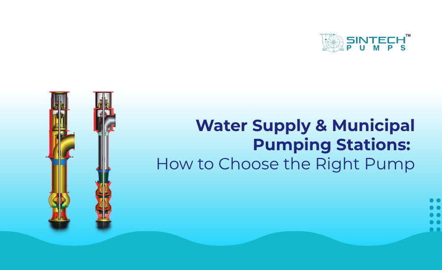
Vertical pumps (SVAF, SVMF, SVT) are the answer when the pump has to drop below the pump floor. Wet pit installs, where the hydraulic floor sits well under the building floor. The motor stays above the flood line, and you draw the column straight up to service it.

Either way, CPHEEO (Central Public Health and Environmental Engineering Organisation) guidelines spell out bell mouth submergence depths and approach velocity limits when you design the sump. Get those wrong, and you get air entrainment and vortexing. Both wreck performance, and over time, the vibration can shake a pump apart. Sintech offers sump design consultancy as part of its technical support, which is worth a lot to an EPC contractor or a state utility doing a big station for the first time.

Sintech’s SMF Horizontal Mixed Flow Pump lands in a genuinely useful spot for mid-sized municipal stations. Flows from 500 m³/hr to over 8,000, heads from 6 to 20 metres. It handles the transition duty between raw water intake and first-stage treatment well, and its mixed flow impeller gives a flatter efficiency curve than an axial would. So it forgives flow variation more readily, which matters a lot when demand swings between the morning peak and the dead of night.

[ultimate_heading main_heading=”What role does energy efficiency play in municipal pump selection?” alignment=”left” margin_design_tab_text=””][/ultimate_heading]

Energy is the single biggest running cost in municipal supply after staffing. The Bureau of Energy Efficiency (BEE), India, reckons pumping systems eat 50 to 70 percent of total electricity in water and wastewater utilities. So efficiency isn’t a nice-to-have. It’s where the money is.

And here’s where tender evaluators trip up all the time. They optimise on capital cost, the sticker price, and call it a day. Run the lifecycle numbers, and it looks different. A pump with 3% better hydraulic efficiency on a 75 kW motor saves you something like ₹60,000–75,000 a year at Indian industrial tariffs. Over a 20-year life that’s past ₹12 lakh, on one pump. Four duty pumps in a station, and the gap’s over ₹50 lakh by the time the project’s done.

This is where Sintech’s Split Casing Double Suction Pumps (SCS) earn their keep. The double-suction impeller balances hydraulic forces on both sides, cutting the axial thrust on the bearings. Lower bearing loads, lower mechanical losses, longer bearing life. Less downtime, lower lifecycle cost. The SCS range is tested to IS 9137 / ISO 9906 acceptance standards, so the efficiency figures on the datasheet are verified, not somebody’s hopeful estimate.

For anything under the Jal Jeevan Mission, the Smart Cities Mission, or a state urban water scheme, sourcing from ISO 9001-certified manufacturers with documented test performance, hydrostatic testing, and performance curve testing is more and more a hard clause in the tender these days. Sintech, based in Ghaziabad, Uttar Pradesh, has held ISO 9001 since its early production years and runs IS 9137 performance testing in its own in-house facility.

[ultimate_heading main_heading=”Common pump selection mistakes in water supply projects” alignment=”left” margin_design_tab_text=””][/ultimate_heading]

Even good engineers make specification errors that only show up after commissioning. These are the ones I see come up again and again on municipal projects.

Picking on availability instead of duty point. A split casing pump that happens to be in stock locally gets shoehorned into a duty that really wanted a mixed flow or axial flow pump. Run it well off BEP, and you’ve got hydraulic surging, heavy vibration, and a failed seal inside 12–18 months.

Ignoring the NPSH Available at the sump. Net Positive Suction Head Available (NPSHa) has to clear the pump’s NPSHr (required) by a safe margin. CPHEEO says at least 0.5 metres for clean water. Skip it, and cavitation eats the impeller in months. Worst at raw water intakes, where the level rises and falls with the season.

Under-specifying for peak demand. Design for average daily demand and forget the peak hourly factor (usually 1.5 to 2.5 times average), and the station falls short during the morning peak. Which is precisely when the complaints land.

Spec’ing identical duty and standby pumps with no way to trim flow. Where demand moves around a lot, VFD (Variable Frequency Drive) compatibility needs to be on the table from day one. Not every pump stays stable across a wide speed range. Axial flow pumps, especially with limited turndown, you don’t run them below 70–75% of design speed without a stability check first.

Overlooking the civil-to-pump interface. The pump you choose drives sump dimensions, suction pipe sizing, and foundation loads. Leave that till late in the civil design, and you can end up with an awkward install that fights you on maintenance access for twenty-odd years.

[ultimate_heading main_heading=”Sintech: water pump manufacturers in India for municipal infrastructure” alignment=”left” margin_design_tab_text=””][/ultimate_heading]

For municipal and infrastructure engineers sizing up water pump suppliers, here’s the relevant Sintech range.

SAF and SVAF axial flow pumps for the high-volume, low-head raw water intake duties. Horizontal and vertical builds, flow capacities from small-town supply right up to large irrigation lift stations.

SMF horizontal mixed flow pump for the mid-range municipal duties. Flows from 500 to 8,000-plus m³/hr at 6 to 20 metres TDH, a broad efficiency curve that copes with the daily swings.

SCS split casing double suction pump for clear water, booster, and high-lift work. High efficiency, low maintenance, IS 9137-tested performance for procurement compliance.

SVT vertical turbine pump for deep tube well and infiltration gallery duties. Good for heads past 200 metres across multiple stages, a regular on groundwater schemes across western and northern India.

As one of the established water pump manufacturers in India, Sintech works directly with EPC contractors, state utility engineers, and municipal corporations at the specification stage. Not just when the purchase order lands. Getting in that early is how you make sure the pump fits the actual site, and not just whatever happened to be in the catalogue.

So for anyone weighing up the best water pump company in India for a municipal project, the fact that Sintech can do sump design consultancy, factory acceptance testing to IS 9137, and post-commissioning service support is reason enough to bring them in early.

[ultimate_heading main_heading=”Conclusion” alignment=”left” margin_design_tab_text=””][/ultimate_heading]

Municipal water infrastructure is long-term public money. A station you design today is expected to run 20 to 25 years, through shifting demand, changing water levels, and energy costs that never sit still. The pump at the heart of it carries a lot of that weight.

The right municipal water pump isn’t the cheapest line in the tender. It isn’t the one with the fastest delivery either. It’s the one matched properly to your hydraulic duty point, with verified efficiency data, the right impeller geometry, and a manufacturer that’ll stand behind it through its working life.

[ultimate_heading main_heading=”Frequently Asked Questions” alignment=”left”][/ultimate_heading]

1. Which type of pump is best for a municipal water supply pumping station?

The right pump depends on the duty point. Axial flow pumps suit high-flow, low-head raw water intake. Mixed flow or split casing pumps suit mid-range distribution duties. Vertical turbine pumps suit deep tube well sources. Matching the pump type to the specific TDH and flow requirement is the most important selection decision.

2. What is an axial flow pump, and when is it used in water supply systems?

An axial flow pump moves water along the shaft axis using a propeller-type impeller. It is used where very high flow rates (500–20,000+ m³/hr) are needed at low differential heads (2–10 metres), typically at river, canal, or reservoir intake pumping stations feeding water treatment plants.

3. How do I calculate the right pump size for a municipal pumping station?

Start with the design flow rate (based on population and per capita demand with a peaking factor of 1.5–2.5x). Calculate TDH by adding static head and friction losses. Plot the duty point on the pump’s H-Q curve and select the pump whose Best Efficiency Point (BEP) falls nearest to your duty point.

4. What standards should a municipal water pump comply with in India?

Municipal water pumps in India should comply with IS 9137 for acceptance testing and performance verification. Manufacturer quality systems should be ISO 9001 certified. For centrifugal process pumps, ISO 2858 and DIN 24255 are the applicable design standards. CPHEEO guidelines govern sump design and civil interface requirements.

5. Why is energy efficiency important in municipal pump selection?

Pumping systems account for 50–70% of total electricity consumption in water utilities (BEE, India). A 3% improvement in hydraulic efficiency on a 75 kW pump saves approximately ₹60,000–75,000 per year. Over a 20-year project life, this can exceed ₹12 lakh per pump, making efficiency a critical lifecycle cost factor, not a secondary consideration.

6. What is the difference between a horizontal axial flow pump and a vertical axial flow pump?

Both move high volumes of water at low heads. The horizontal (SAF) configuration suits installations with adequate floor space and a horizontal suction approach channel. The vertical (SVAF) configuration is used in wet pit installations where the motor must remain above the flood level and floor space is limited. It pulls water upward through a column assembly.

Hitesh No Comments

Types of pumps used in the sugar industry: from juice extraction to molasses handling

Table of Contents

  1. The short answer: what centrifugal pumps a sugar mill actually runs
  2. Why is sugar one of the hardest fluids to pump
  3. Cane handling and the first stage of processing sugar cane
  4. Juice extraction and the juice transfer pump problem
  5. Clarification, evaporation, and where centrifugal pumps earn their keep
  6. The molasses pump challenge nobody warns you about
  7. Condensate, vacuum, and effluent: the supporting cast
  8. How Sintech approaches sugar mill pumping
  9. Frequently asked questions

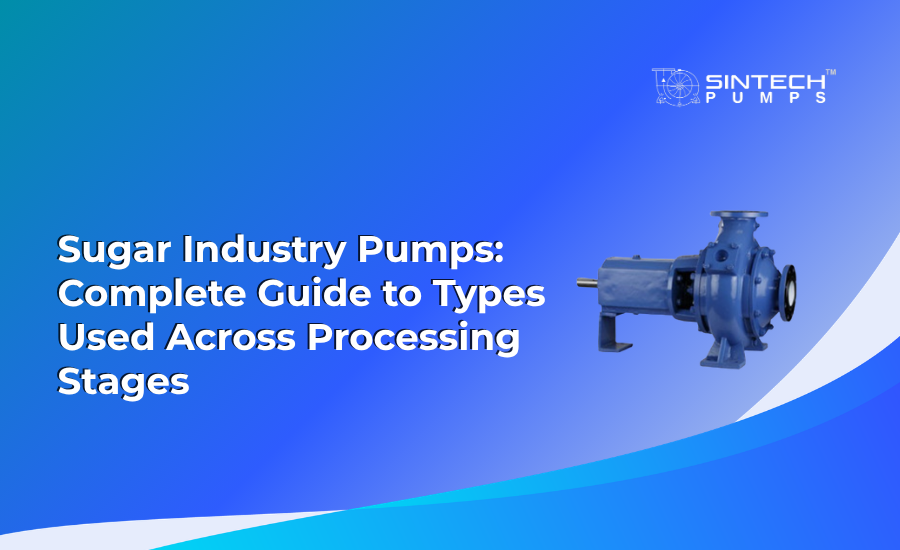
Sugar mills use different pumps at each processing stage because the fluid changes throughout. Mixed and axial flow pumps handle cane washing water. Dynamic sealing pumps and juice transfer pumps move abrasive raw juice. Centrifugal pumps handle clarified juice and syrup. Torque flow pumps move thick molasses and massecuite. Multistage and liquid ring vacuum pumps serve boiler feed and vacuum pans.

[ultimate_heading main_heading=”The short answer: what centrifugal pumps a sugar mill actually runs” alignment=”left” margin_design_tab_text=””][/ultimate_heading]

A sugar mill does not run on one pump. The types of pumps used in the sugar industry processing change at almost every stage, because the fluid changes at every stage. Thin cane juice behaves nothing like thick massecuite, and molasses behaves nothing like either. A mill typically relies on juice transfer pumps, process centrifugal pumps, dynamic sealing pumps, torque flow pumps, and dedicated molasses pumps. This guide walks through each one, where it sits in the line, and why the wrong choice quietly costs you money.

If you run maintenance at a sugar plant, you already know the pain. A seal fails on a Tuesday during peak crushing, and suddenly you are losing tonnes of throughput while a fitter hunts for spares. Most of those failures trace back to a single decision made years earlier: a pump picked because it fit the budget, not because it fit the fluid. Sintech Pumps, headquartered in Ghaziabad, Uttar Pradesh, has been engineering for exactly this problem since 1986, and the pattern repeats across the UP sugar belt every season.

So let’s go stage by stage.

[ultimate_heading main_heading=”Why is sugar one of the hardest fluids to pump” alignment=”left” margin_design_tab_text=””][/ultimate_heading]

Here’s what gets overlooked. Sugar processing isn’t one fluid duty. It’s a dozen.

Raw juice carries bagasse fibre, sand, and grit straight off the cane. Clarified juice is cleaner but acidic. Syrup gets viscous as water boils off. Massecuite is a thick slurry of crystals and mother liquor. And final molasses? It can hit viscosities that make ordinary pumps stall, overheat, or tear their seals apart.

A single sugar pump specification rarely covers all of this. That’s the core reason sugar mills carry such a wide mix of pump types. The fluid dictates the machine, not the other way around. Temperature matters too. Much of this happens hot, sometimes above 100°C in the evaporator and pan stations, which rules out a lot of standard sealing arrangements that would cook and fail.

Once you accept that the duty drives the choice, the rest of the line makes sense.

[ultimate_heading main_heading=”Cane handling and the first stage of processing sugar cane” alignment=”left” margin_design_tab_text=””][/ultimate_heading]

The journey starts before any juice exists. When you’re processing sugar cane, the early stages involve washing, imbibing water, and moving large volumes of dirty water around the mill yard.

This is high-flow, low-head territory. You’re not building pressure; you’re shifting volume. Mixed flow and axial flow pumps handle this well because they’re built to move a lot of liquid against modest resistance. Sintech’s horizontal mixed flow pumps (SMF) and axial flow pumps (SAF/SVAF) are designed for these large-volume duties, where the water often carries trash and suspended solids that would clog a tighter machine.

Get this stage wrong, and you’ll see it downstream. Undersized water handling chokes imbibition, and poor imbibition hurts extraction. The pumps here look humble, but they set the tone for the whole crush.

[ultimate_heading main_heading=”Juice extraction and the juice transfer pump problem” alignment=”left” margin_design_tab_text=””][/ultimate_heading]

Now the real work begins. Once the mills crush the cane, you have raw juice, and you need to move it fast, hot, and full of fibre.

A juice transfer pump at this stage faces a nasty combination: suspended bagacillo, abrasive grit, and a fluid that foams easily. Conventional centrifugal pumps with standard mechanical seals struggle here. The abrasives chew through seal faces, and the fibre wraps around closed impellers until flow drops off.

This is where the sugar pump choice gets interesting. Many Indian mills have moved to dynamic sealing pumps for juice duty precisely because they remove the mechanical seal from the equation. Instead of a seal that wears against the abrasive juice, the pump uses a repeller-based dynamic sealing arrangement that keeps liquid back during operation. No seal face to fail means one of the most common downtime causes simply disappears.

Sintech’s dynamic sealing pump range was built for this exact juice extraction problem. For a mill crushing 5,000 tonnes of cane a day, even a few hours of unplanned seal-related stoppage during peak season is throughput you never recover. Removing the seal removes the headache.

A good juice transfer pump also needs an open or semi-open impeller so fibre passes through instead of building up. That’s a small detail on a datasheet and a huge difference on the shop floor.

[ultimate_heading main_heading=”Clarification, evaporation, and where centrifugal pumps earn their keep” alignment=”left” margin_design_tab_text=””][/ultimate_heading]

After extraction, the juice gets limed, heated, and clarified. From here on, the fluid is cleaner, and this is the heartland of process centrifugal pumps.

Clear juice transfer, sulphured juice handling, and syrup transfer to the evaporators all use centrifugal pumps sized for specific flow and head. These duties run continuously through the crushing season, so efficiency matters enormously. A pump operating well off its Best Efficiency Point (BEP), the flow rate where it runs most efficiently, wastes energy every single hour it runs.

Here’s a number worth keeping in mind. A 5% improvement in pump efficiency on a 75 kW motor running through a full season can save roughly ₹80,000 to ₹1,00,000 in electricity, going by typical Indian industrial tariffs. Across a mill’s full pump inventory, the figure climbs fast. That’s why serious industrial centrifugal pump manufacturers design to standards like ISO 2858 and ISO 5199, which govern dimensions and reliability for chemical and process duty, and test to IS 9137, India’s acceptance testing standard for pump performance.

Sintech’s centrifugal process pumps (CPS) follow these standards, which matters when a procurement team needs to compare specs honestly rather than trust a brochure. Standards aren’t bureaucracy here. They’re how you know the pump will actually deliver the head and flow it promises.

As syrup thickens through the evaporator effects, viscosity climbs, and pump selection has to account for that. A pump perfect for thin, clear juice may underperform badly on heavy syrup. This is the trap of buying one “general-purpose” sugar pump and hoping it covers everything.

[ultimate_heading main_heading=”The molasses pump challenge nobody warns you about” alignment=”left” margin_design_tab_text=””][/ultimate_heading]

Then there’s molasses. And molasses is where a lot of pump selections fall apart.

Final molasses is thick, sticky, and stubborn. At ambient temperature in a North Indian winter, it can become almost intractable. A standard centrifugal machine fights this fluid the whole way, drawing excess power and running hot. A proper molasses pump has to be built for high viscosity and high solids content from the start.

For the thickest duties, massecuite, magma, and heavy molasses laden with crystals, torque flow pumps do the job. A torque flow pump uses a recessed impeller, meaning the impeller sits back out of the main flow path. The fluid moves through a vortex action rather than being forced through tight impeller passages. That design lets it pass thick, crystal-bearing, solids-laden fluid that would jam a conventional pump solid.

Sintech’s torque flow pumps (STF) are specified for these plugging, abrasive, high-viscosity duties across sugar plants. The trade-off is honest: a torque flow pump runs at lower hydraulic efficiency than a standard centrifugal pump because of how it moves fluid. But on a duty where a standard pump simply clogs or fails, lower efficiency on a pump that runs beats high efficiency on a pump that’s stripped down for repair. Reliability wins.

A well-chosen molasses pump also saves you grief at season’s end, when residual molasses cools and sets. Pumps that can be drained and cleaned easily are worth the price difference every December.

[ultimate_heading main_heading=”Condensate, vacuum, and effluent: the supporting cast” alignment=”left” margin_design_tab_text=””][/ultimate_heading]

A few duties don’t get much attention, but keep the mill running.

Boiler feed needs multistage high-pressure pumps to push water against the steam-side pressure of the cogeneration plant. Sintech’s multistage high-pressure pumps handle this boiler feed duty, where each stage adds head to reach the pressures a modern bagasse-fired boiler demands.

Vacuum pans need vacuum, and that’s where liquid ring vacuum pumps come in, maintaining the low pressure that lets sugar crystallise at lower temperatures. And every mill has effluent. Spent wash, floor washings, and process effluent all need handling, and tighter environmental rules across Maharashtra, UP, and Tamil Nadu are pushing mills toward zero liquid discharge systems for this stream.

These aren’t glamorous duties. But a vacuum pump that can’t hold a pan vacuum will quietly drag down your sugar recovery, and you’ll spend weeks blaming everything else first.

[ultimate_heading main_heading=”How Sintech approaches sugar mill pumping” alignment=”left” margin_design_tab_text=””][/ultimate_heading]

What separates a real solution from a catalogue sale is matching each duty to the right machine rather than forcing one pump across the whole line.

Sintech Pumps has supplied this sector for nearly four decades, working with names like Balrampur, Dhampur Sugar Mills, Triveni, and NSL Sugar. That field experience shapes the recommendations: dynamic sealing pumps for abrasive juice, torque flow pumps for molasses and massecuite, standards-compliant centrifugal pumps for clean process duty. As an ISO 9001-certified manufacturer building to ISO 2858, ISO 5199, and IS 9137, the engineering meets the same bar as imported brands while being made and serviced in India, which means faster spares and faster site support when crushing season can’t wait.

[ultimate_heading main_heading=”Frequently Asked Questions” alignment=”left”][/ultimate_heading]

1. What are the main types of pumps used in sugar industry plants?

A sugar plant mainly uses juice transfer pumps, centrifugal process pumps, dynamic sealing pumps, torque flow pumps for massecuite, and molasses pumps. Each matches a specific fluid as it thickens through processing, from thin mixed juice to dense final molasses.

2. Which pump is best for moving raw mixed juice?

A dynamic sealing pump or non-clogging juice transfer pump is ideal for raw mixed juice. Because the juice carries bagasse fibre, a sealless design avoids the mechanical seal failures that commonly stop conventional centrifugal pumps during crushing.

3. Why are torque flow pumps used for massecuite?

Massecuite is a thick slurry of sugar crystals. A torque flow pump uses a recessed impeller, so fluid moves by vortex action without direct contact. This passes fragile crystals and solids without clogging or grinding them, which standard pumps cannot do.

4. What type of pump handles molasses?

Final molasses is dense and sticky, so it needs a dedicated molasses pump built for high viscosity, with wide internal clearances and a correctly sized drive. Torque flow or positive-displacement designs suit the heaviest grades, especially during colder weather.

5. Are centrifugal pumps used in sugar processing plants?

Yes. Centrifugal pumps handle clarified juice, syrup, cooling water, and general process duty across a sugar processing plant. The key is correct sizing near the Best Efficiency Point and adequate suction margin, which is where experienced industrial centrifugal pump manufacturers add value.

6. Does Sintech supply pumps for the full sugar process?

Yes. Sintech manufactures juice transfer pumps, centrifugal process pumps, dynamic sealing pumps, torque flow pumps, molasses pumps, boiler feed, and cooling water pumps. Built to ISO 9001 and IS 9137, the range covers every stage of a sugar plant from a single Indian manufacturer.